Chest Radiograph
Author: William Krantz, MD, West Virginia University School of Medicine, Department of Radiology
Editor: Matthew Tews, DO, MS, Medical College of Wisconsin, Department of Emergency Medicine
Objectives
At the end of this chapter, the student will be able to:
- Identify details to verify when looking at radiologic imaging
- Assess adequacy of chest radiographs
- Develop a systematic approach to reading chest radiographs
- Identify important signs to know when reading chest radiographs
- Understand the importance of knowing common diagnoses on the chest radiograph
Introduction
Section 1: Verify Details
Although mistakes are rare, they do occur and you should verify details pertaining to your patient on every study you review.
- Patient – Ensure the study was performed on the correct patient.
- Time and date – Note the time and date of the study. This is especially important if there are comparison studies. By convention, the older study is displayed on the left, though this is not always the case.
- Study type – Verify the type of study performed. Sometimes a study will be changed depending on what the patient can tolerate. For example an AP supine CXR may be done on a patient that can’t stand for a PA/lat CXR.
- Comparisons – Make sure you view every image submitted. It is not uncommon for multiple views to be taken for an AP supine CXR study on a difficult to position patient. Compare these to previous studies, if available.
Projection
Section 2: Assess Adequacy
PA/lateral projection is the standard used for most patients who are ambulatory and able to stand. In this view, the mediastinum should have a normal width and a good inspiratory effort should results in full diaphragm expansion.
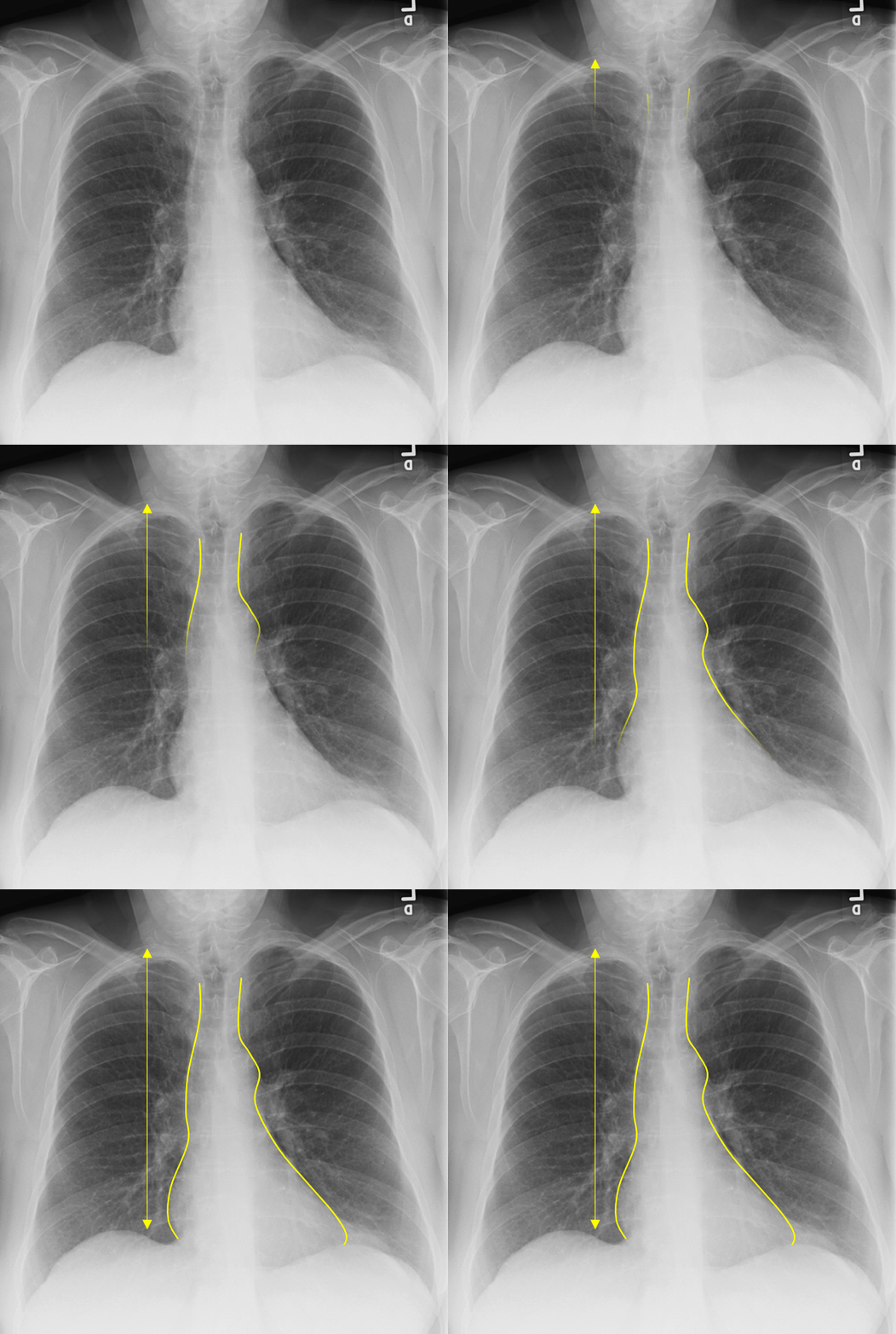
PA Projection – Normal Mediastinum and Good Inspiratory Effort
AP projection is obtained with the patient in bed and lying flat or partly upright. It is usually reserved for non-ambulatory patients. AP projections have the disadvantage of making the heart an mediastinum appear more prominent as well as usually resulting in shallower inspiration which can limit evaluation of the lung bases. A lateral projection is not obtained with a AP projection, thereby limiting the view of the chest further.
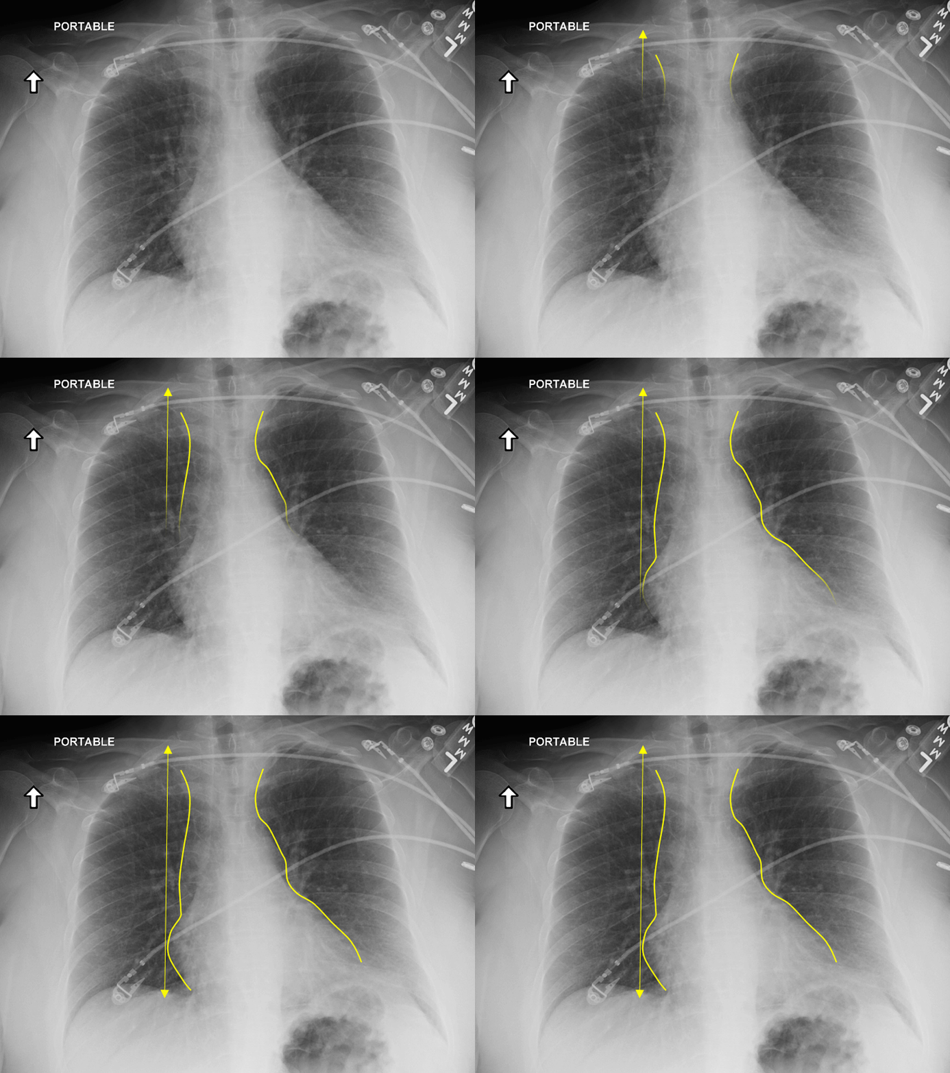
AP Projection – Widened Mediastinum and Less Inspiratory Effort
It is therefore preferable to order a PA/lateral CXR over an AP view when possible.
Rotation
It is not uncommon, especially for AP supine CXRs, for the patient to be slightly rotated. Rotation can be assessed by measuring the distance between the medial edges of the clavicles to the vertebral spinous processes. They should be equal or near equal. Anterior structures move the same direction as rotation so the clavicle/spinous process width is increased on the side to which the patient is rotated. This patient is rotated to the left.
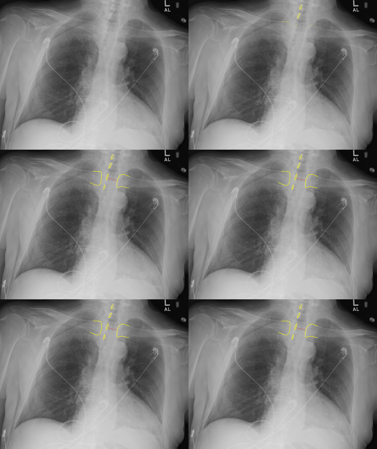
Red Dotted Line = Slight Rotation to the Left
Here is a patient severely rotated to the left. Severe rotation can alter the normal cardiomedistinal contour and make interpretation difficult.
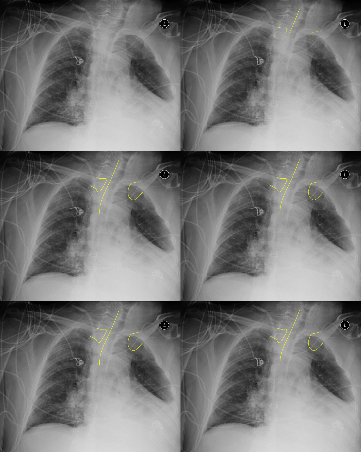
Significant Rotation to the Left
Inspiration
Deeper inspirations show more lung and result in better overall images with less haziness at the lung bases and less enlargement of the heart and mediastinum. A good inspiration on a PA CXR shows at least 9 posterior ribs.
The following films were of the same patient and taken using the same AP projection. The image on the left is a poor inspiratory effort (ribs 1-6), while in the film on the right, the patient achieved a much deeper inspiration on the bottom xray (ribs 1-10).
 |  |
Poor Inspiratory Effort Good Inspiratory Effort
Penetration
Under-penetration results from not enough xrays passing thru to allow differentiation of dense structures, thus the mediastinum and spine appear white. In an over-penetrated CXR too many xrays have passed thru the chest preventing differentiation of low density structures, thus the lung fields appear black. With proper penetration, the spine should be faintly visible behind the heart.
 |  |  |
Under-penetrated Over-penetrated Correctly-penetrated
Section 3: Develop Systematic Approach
It is important to develop a system for looking at imaging and be consistent in its use. Different systems exist, whether it is based on anatomical structure (looking at one structure, then another, and so on) or scanning the image in a pattern (back and forth from top to bottom). No system is best. What is important is finding one that you like and using it consistently. Resist the natural tendency to focus in on the area which first catches your eye otherwise you may miss the more important subtle finding.
ABCDs
The ABCDs approach is taught as an aid for remembering steps in many different learning environments. It can be applied in interpreting chest xrays too. The mneumonic starts with A and can go through H.
| A – Airway | E – Effusion |
| B – Bones | F – Fields |
| C – Cardiac | G – Gastric |
| D – Diaphragm | H – Hila |
A – Airway
- Identify trachea and note if it is midline and straight. A deviated trachea can be caused by many etiologies including rotation and masses.
- Identify carina and estimate the angle. Normally 60-100°. Common things that may increase this angle include left atrial enlargement and adenopathy.
- Trace out right and left mainstem bronchi.
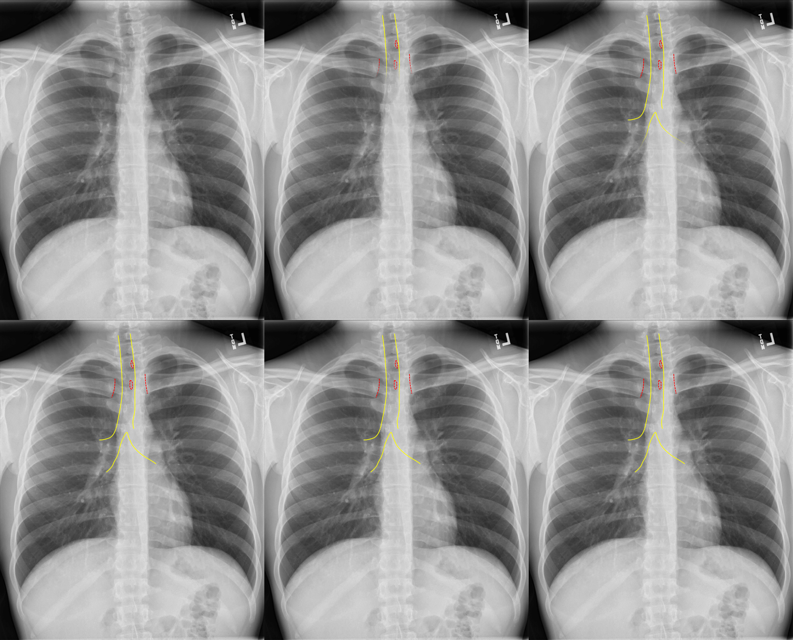
Trachea midline: yellow; Spinous process and medial clavicles: red. This patient is slightly rotated right.
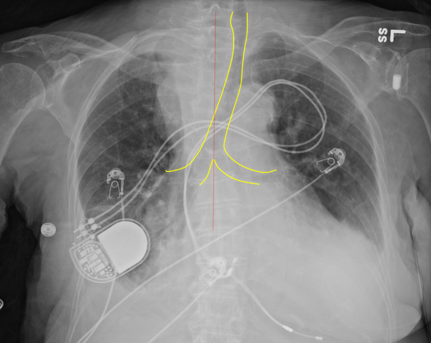
Leftward tracheal deviation due to large substernal goiter
Endotracheal tubes
Endotracheal tube (ETT) tip should sit 3-5cm above the carina. The ETT can be too high above the carina and will need to be advanced, or too deep into the right mainstem and need to be pulled back.
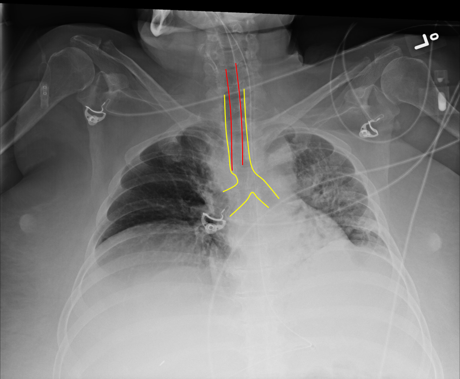
Intubation with Good Position of ETT
Red = ETT; Yellow = Trachea and Bronchi
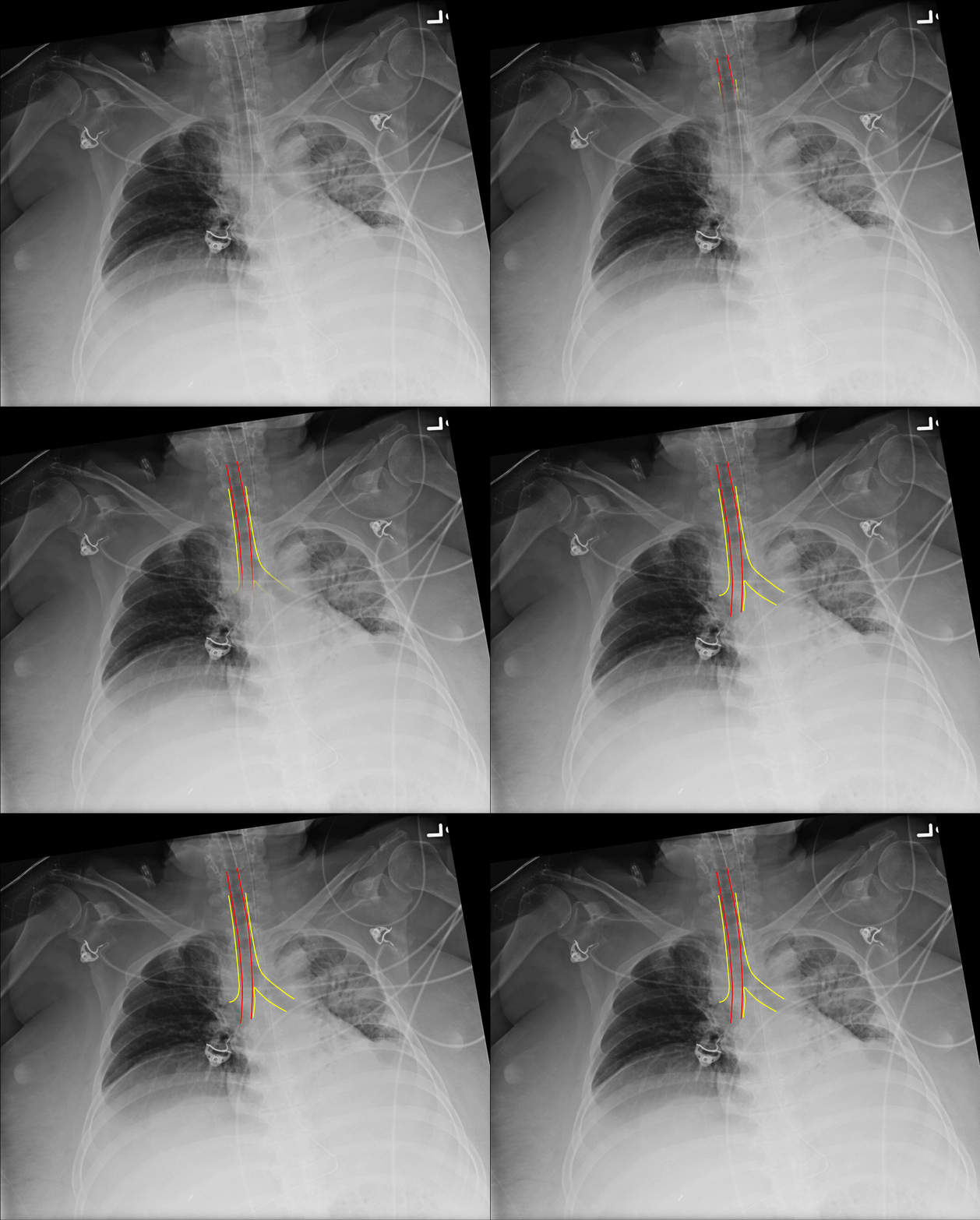
Right mainstem bronchus intubation
B – Bones
Evaluate clavicles, AC joints, GH joints and humeri followed by the ribs and vertebra.
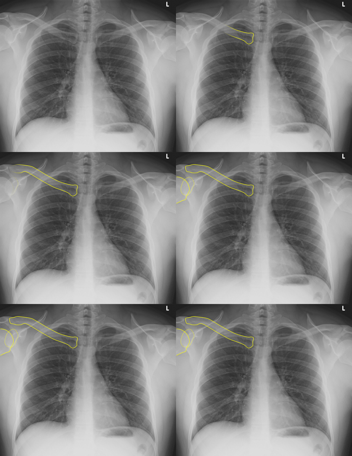
Normal Alignment of Clavicle, Glenohumeral Joint and Proximal Humerus on a PA View of Chest
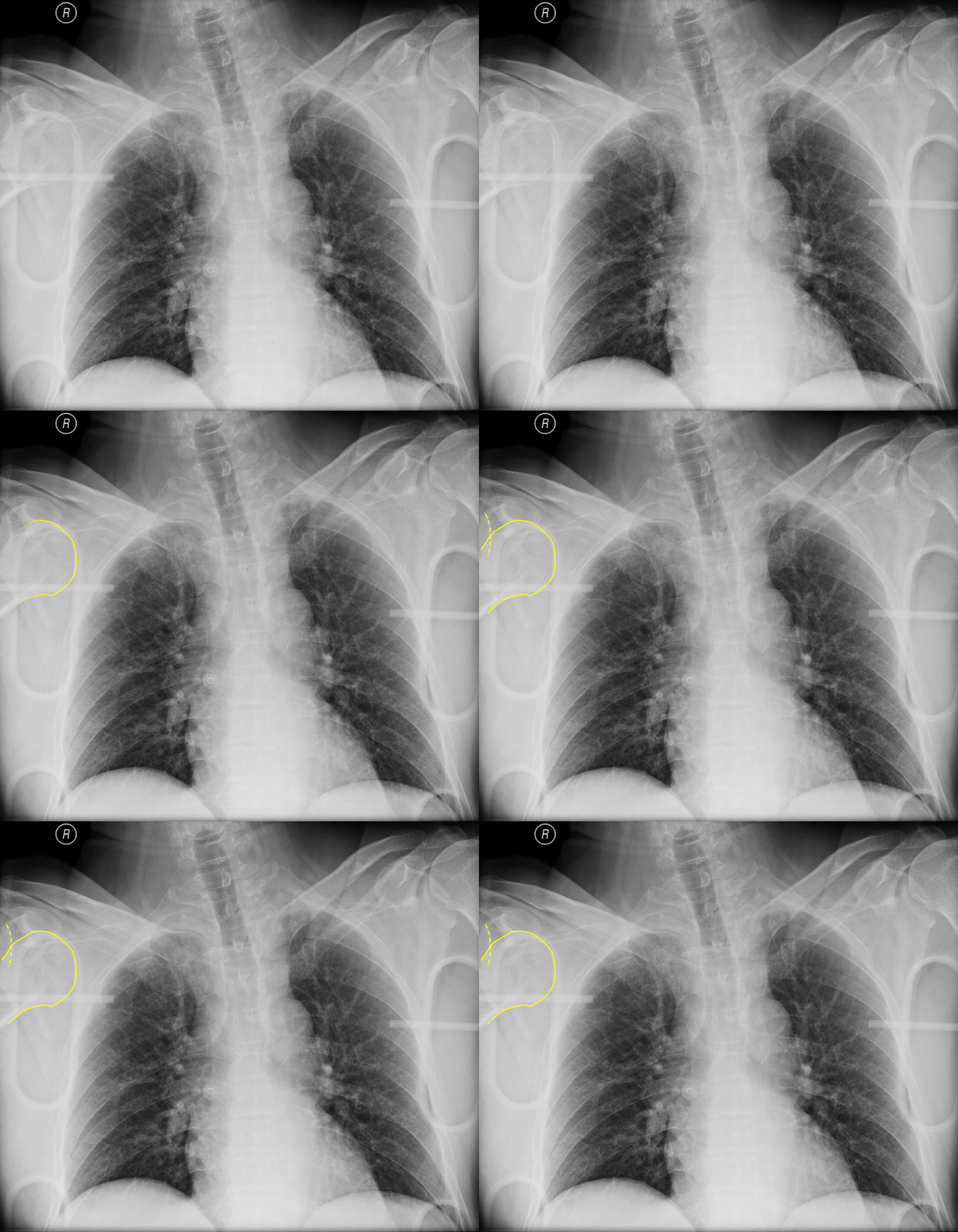
Subtle Anterior Shoulder Dislocation.
The humeral head (solid yellow line) is out of the glenoid fossa (dotted yellow line)
Sometimes, overlying structures on the radiograph can obscure positive findings. If there is suspicion of an injury or abnormality in the region of overlying structures (such as cords, belts, jewelry), remove them and repeat the radiograph.
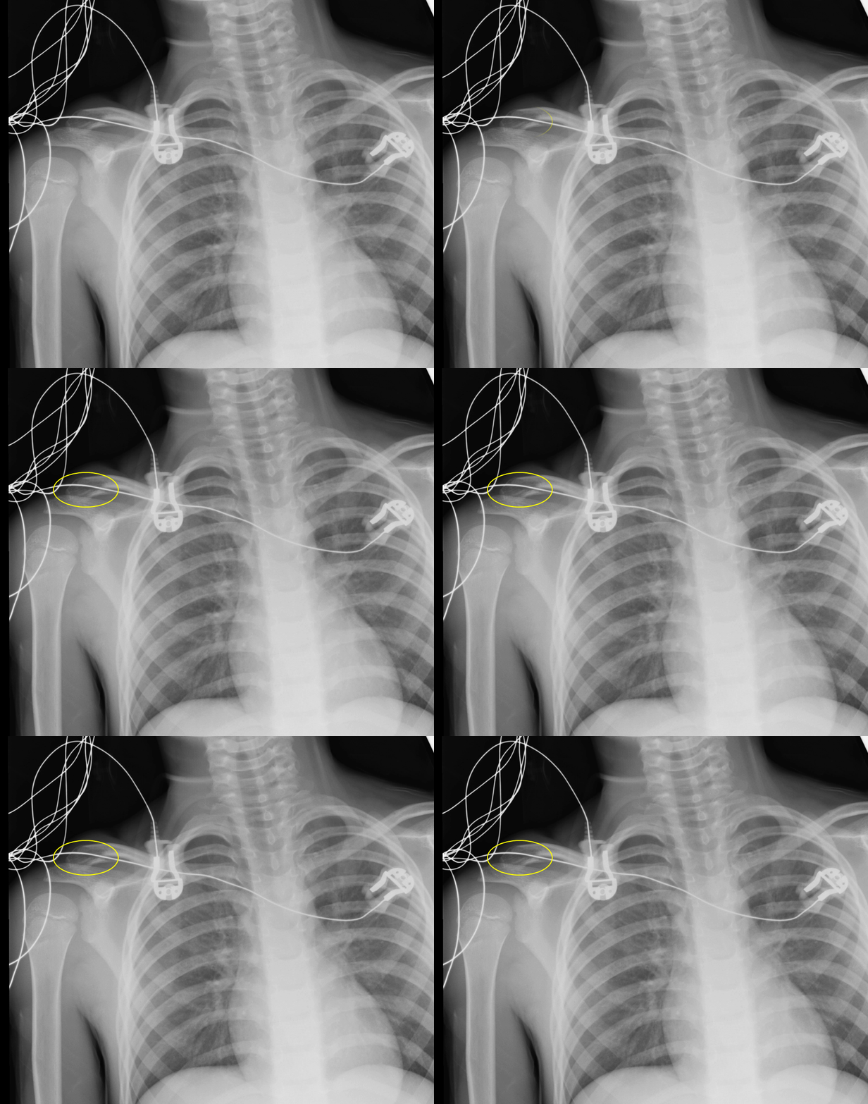
“Normal” Chest Radiograph at First Glance
However, cardiac monitor cords overly the distal clavicle
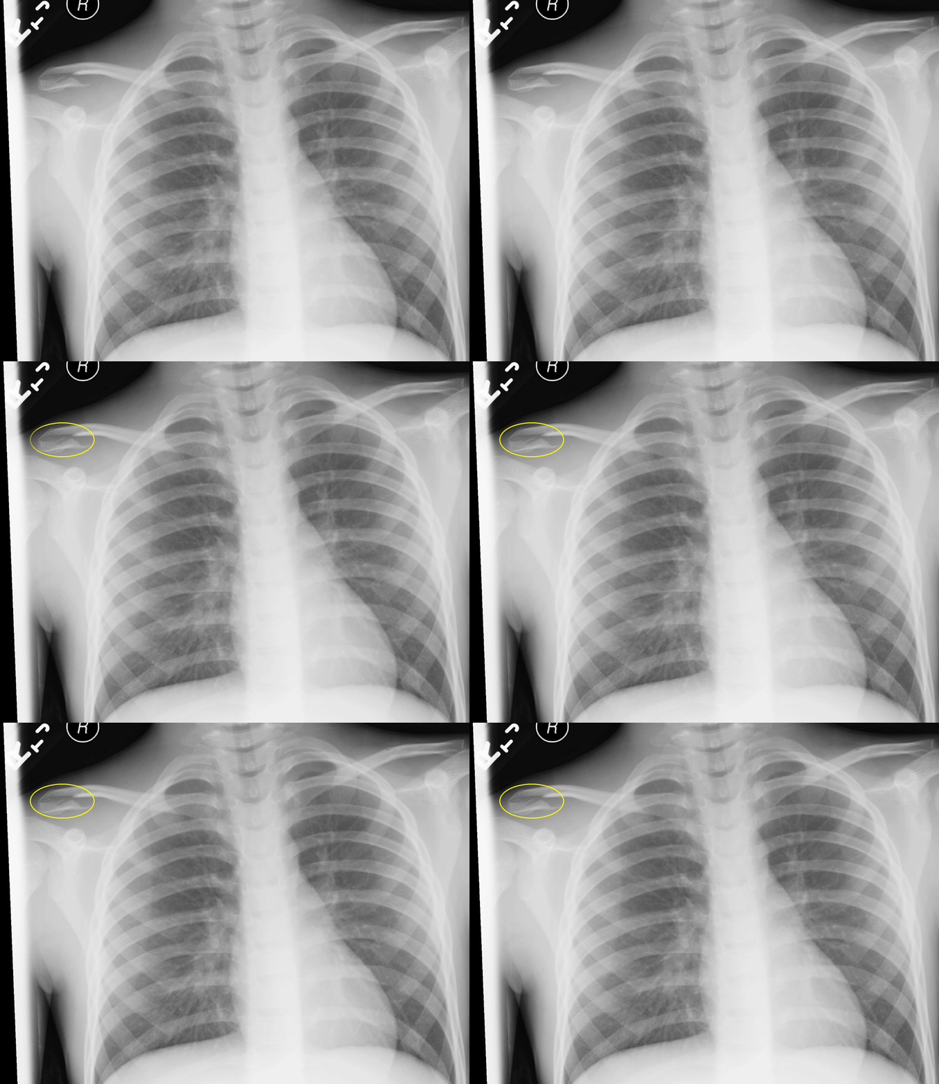
Distal Clavicle Fracture
The film shows a distal clavicle fracture when the monitor cord is removed
Rib fractures can sometimes be extremely subtle. Be sure to trace all the ribs to identify step offs.
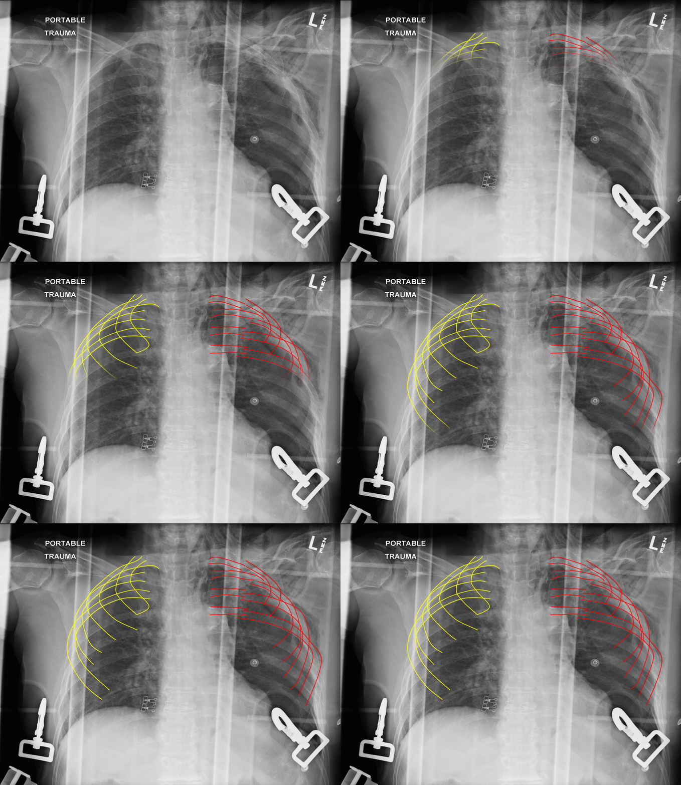
Left Sided Upper Rib Fractures
A useful trick can be to flip the image upside down or sideways which makes the ribs appear to stand out.
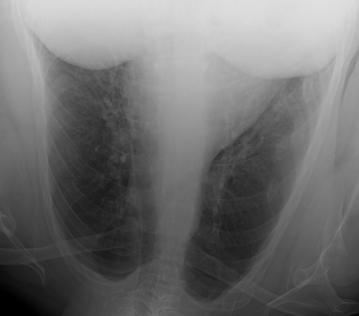
Left Sided Rib Fractures
Visualize the entire spine and look for vertebral body height loss and alignment
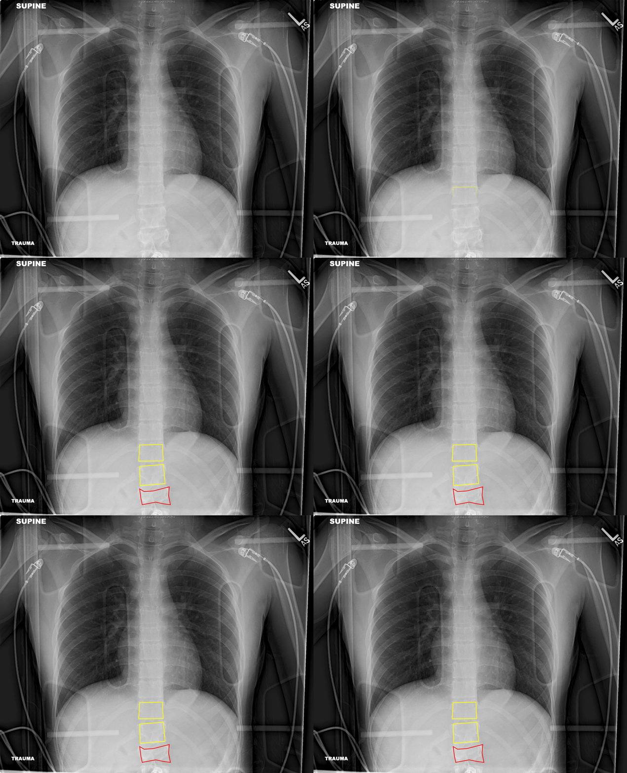
L1 Compression Fracture = Red; T11 and T12 Normal Body Height (Yellow)
C – Cardiac
Next, check the cardiac size: normal is <50% of thoracic diameter on PA projection and <55% on AP projection.
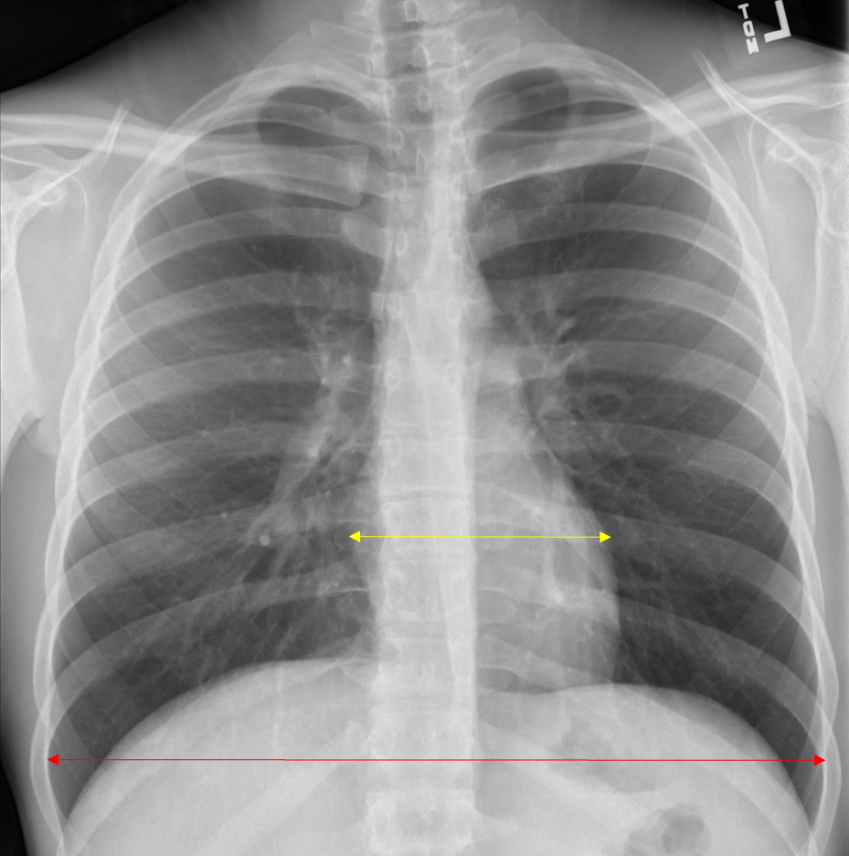
Normal Cardiac Size on PA CXR
Red = thoracic diameter; Yellow = cardiac diameter
Verify cardiac borders are sharp and defined.
Evaluate aorta and AP window (should be concave)
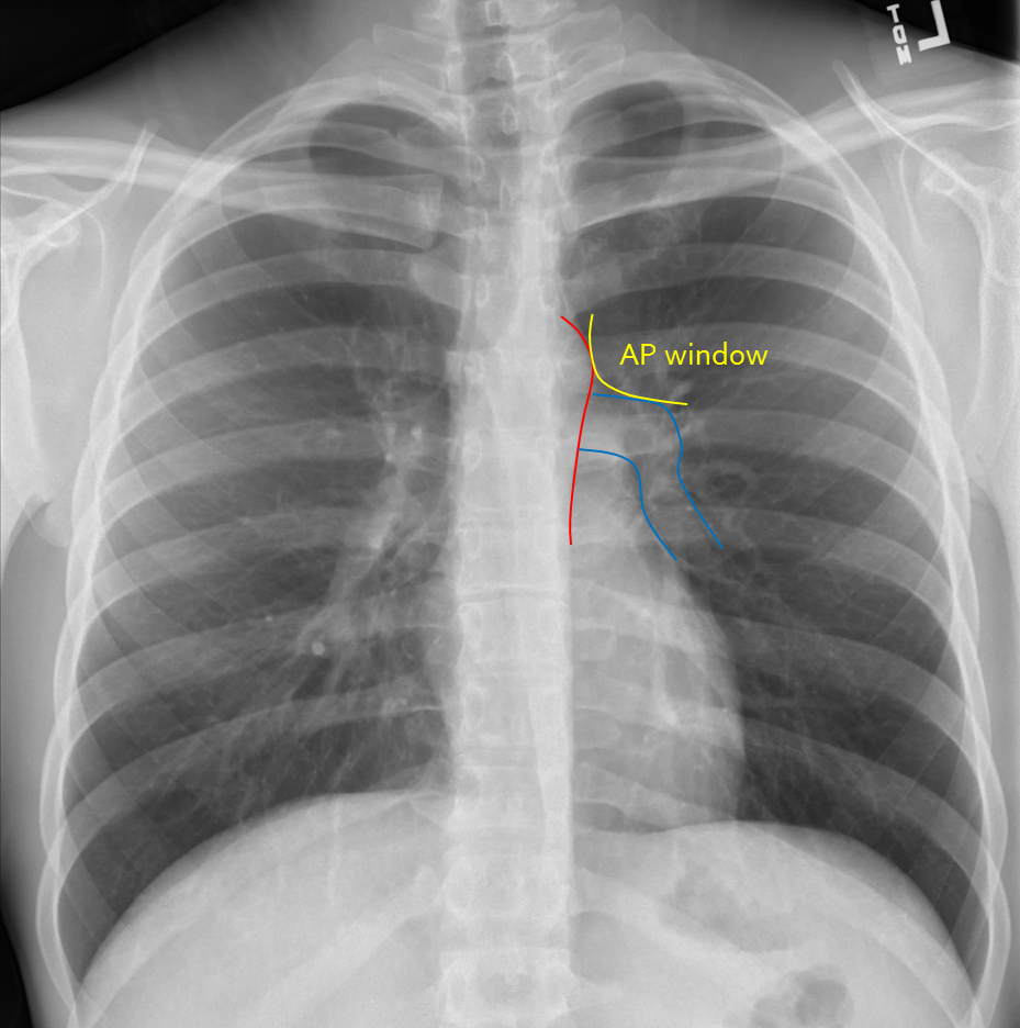
Normal AP Window and Cardiac Border
Red = Aortic contour; Blue = Upper cardiac border; Yellow = AP window
D – Diaphragm
Verify diaphragm and costophrenic angles are sharp and well defined.
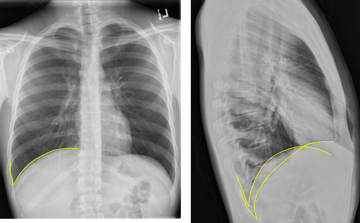
Sharp Diaphragmatic Angles = Yellow
Note any flattening of diaphragm which may indicate hyperexpanded lungs such as seen in a patient with COPD.
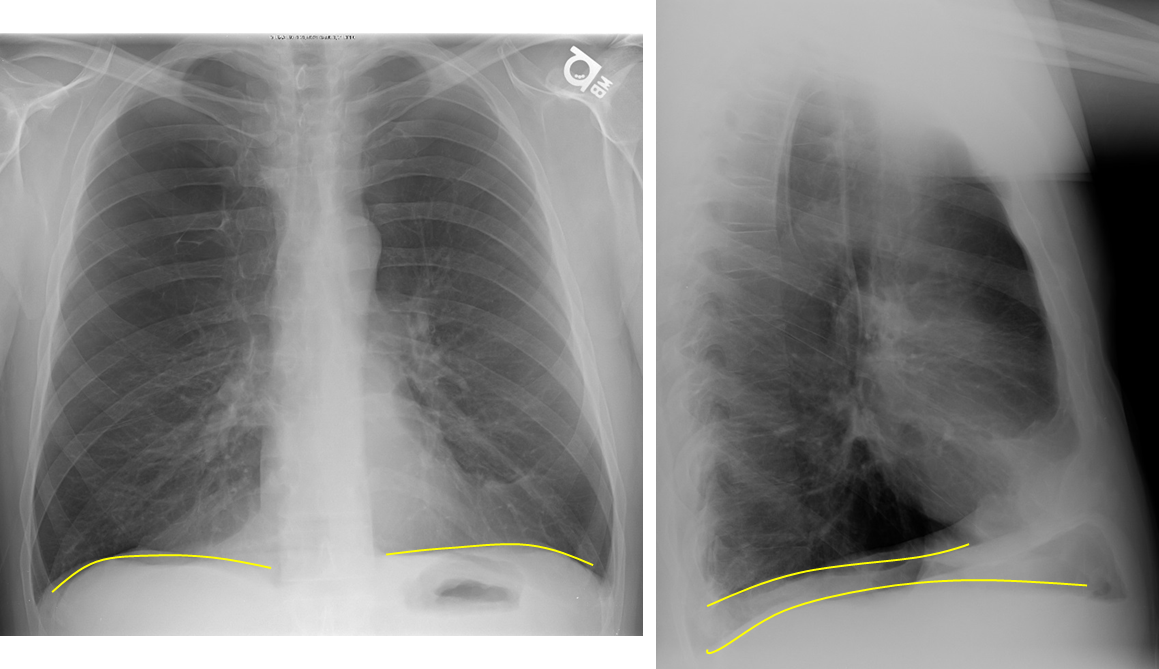
Flattened Diaphragm in COPD = Yellow
Obscuration of all or a portion may indicate pleural effusion or consolidation.
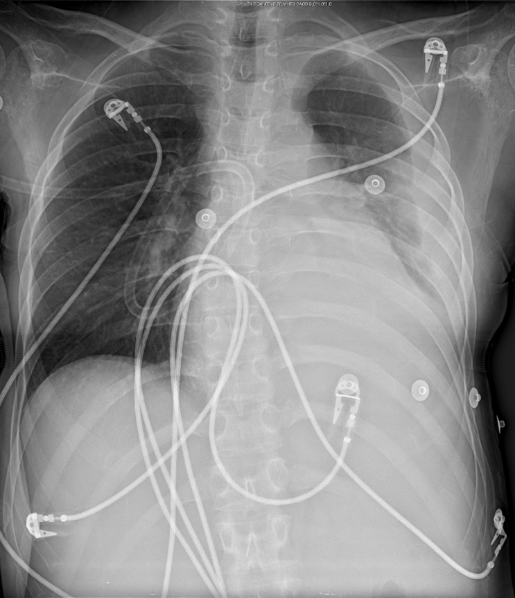
Left Sided Pleural Effusion
Look for free air under diaphragm on upright projections.
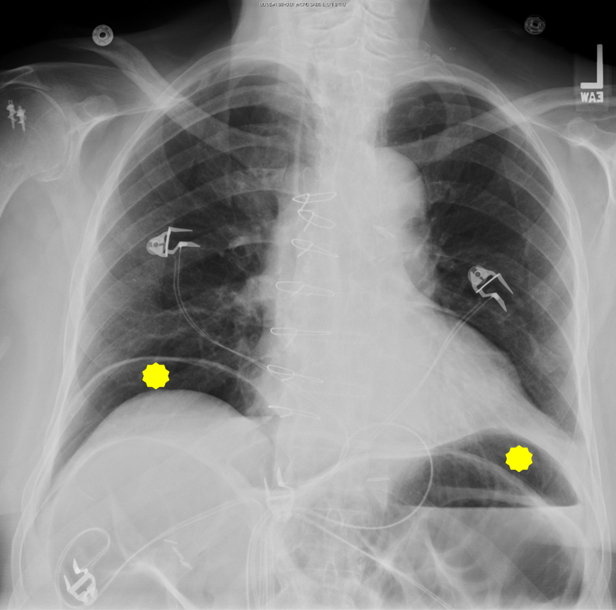
Free Air Under Diaphragm = Yellow
E – Effusion
Look for ‘blunting’ of the costophrenic angles on PA projection and posterior costophrenic sulcus on lateral projection. As much as 300-500cc of fluid may not be seen on PA projection, but seen on lateral projection.
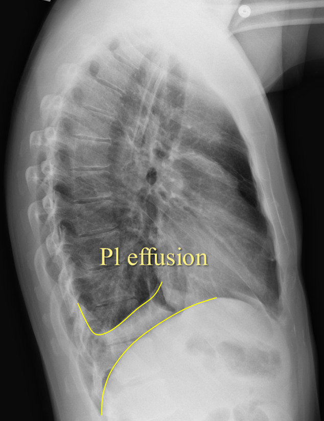
Pleural Effusion on Lateral View
Fluid may track into right minor fissure causing it to thicken or even form a pseudotumor.
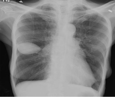
Right Minor Fissure Fluid
Loculated effusion may present as nondependent pleural thickening.
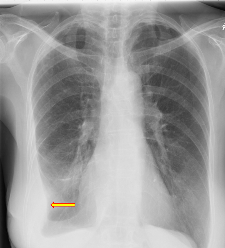
Right Sided Loculated Effusion
F – Fields
Lung fields should generally be uniformly dark grey.
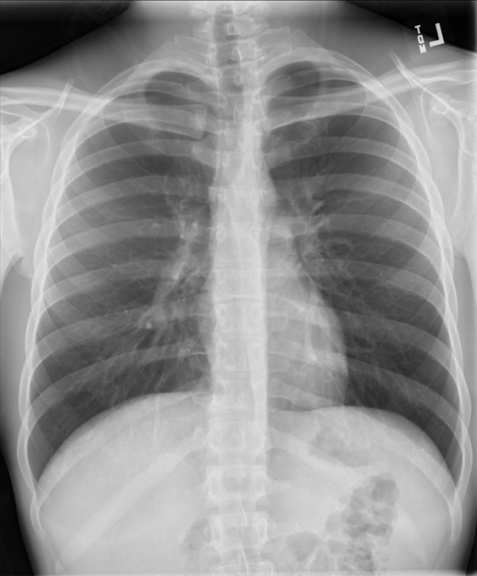
Uniformly Dark Grey Lung Fields
Increased density may be due to airspace disease such as pneumonia, masses, pleural effusions, pulmonary edema, or atelectasis
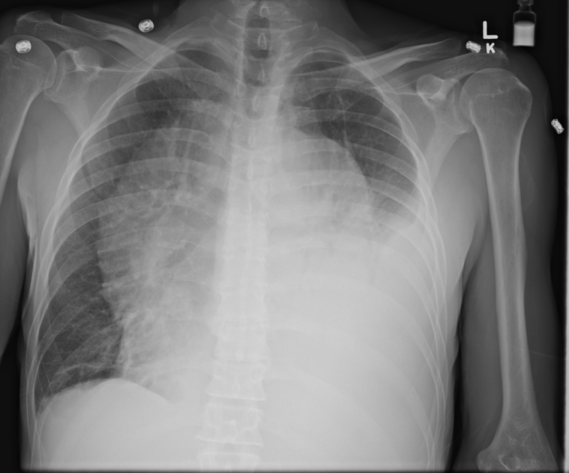
Left Lower Lung with Effusion
Decreased density may be due to pneumothorax or hyperexpansion due to COPD.
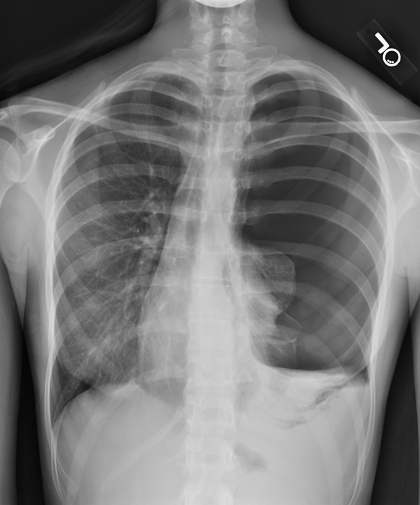
Left Sided Pneumothorax with Tension Component
Heart is being pushed to the right
There are several other findings to look for with the lung fields. Sometimes they are obvious and take over most of the view of the lung fields and other times they are subtle and scattered or singular.
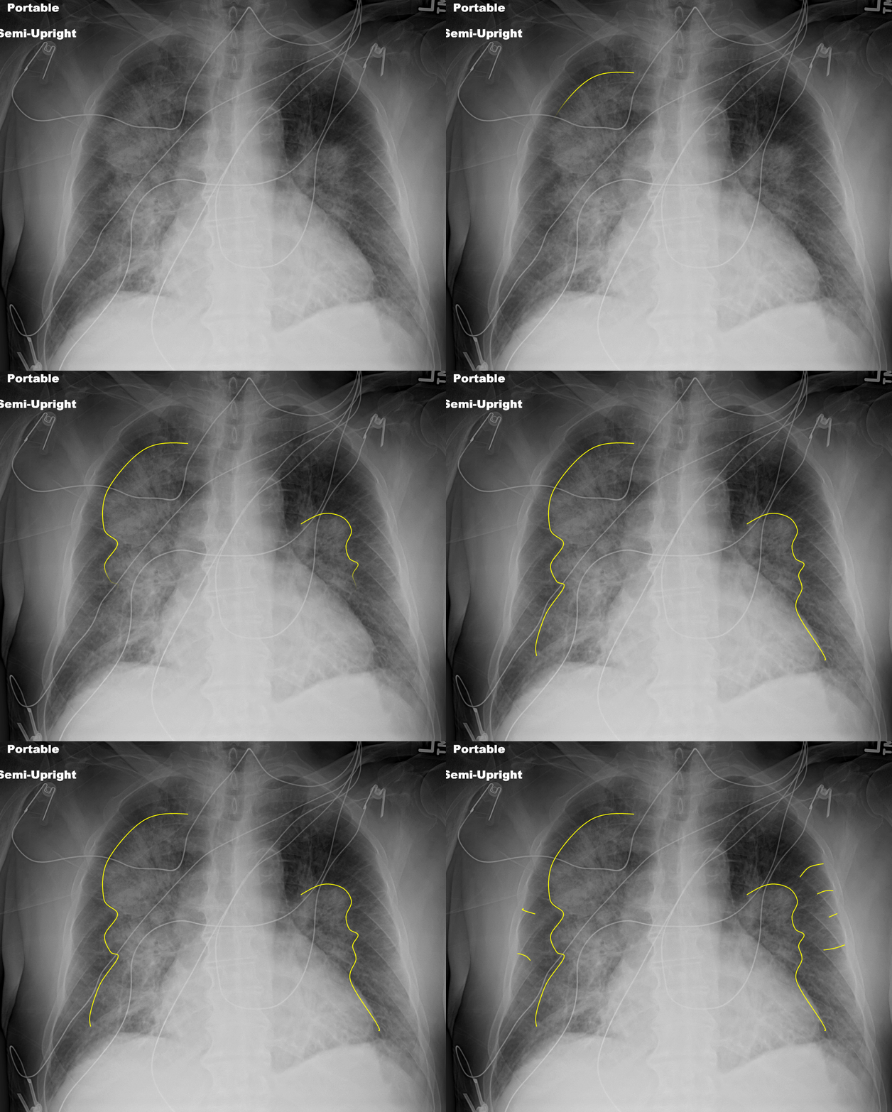
‘Bat-wing’ Pulmonary Edema
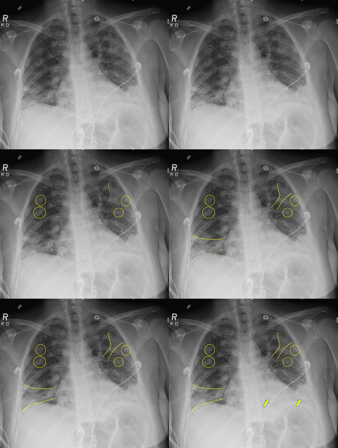
Septic Emboli
G – Gastric
Look for gastric air bubble located in LUQ below the left hemidiaphragm and cardiac silhouette.
Hiatal hernias are very common. Usually seen as a rounded density at the midline behind the heart.
Sometimes an air-fluid level may be seen.
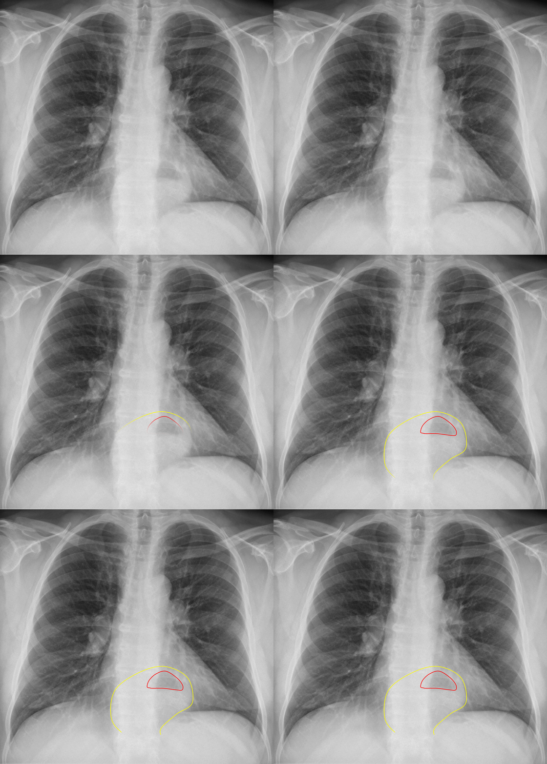
Diaphragmatic Hernia
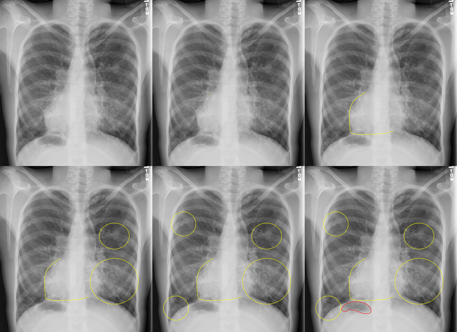
Kartagener’s Disease (dextrocardia, airspace disease, situs inversus)
 |  |
A case that at first glance appears to represent massive cardiomegaly, but closer inspection of the lateral view reveals air density anteriorly that resembles air in the bowel. Finding was suspicious for hernia.
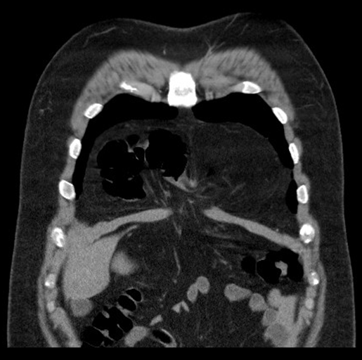
Coronal CT image reveals mesenteric fat and bowel in a large diaphragmatic hernia.
H – Hila
Locate right and left main pulmonary arteries.
Note any obvious contour abnormalities which may indicate masses or adenopathy.
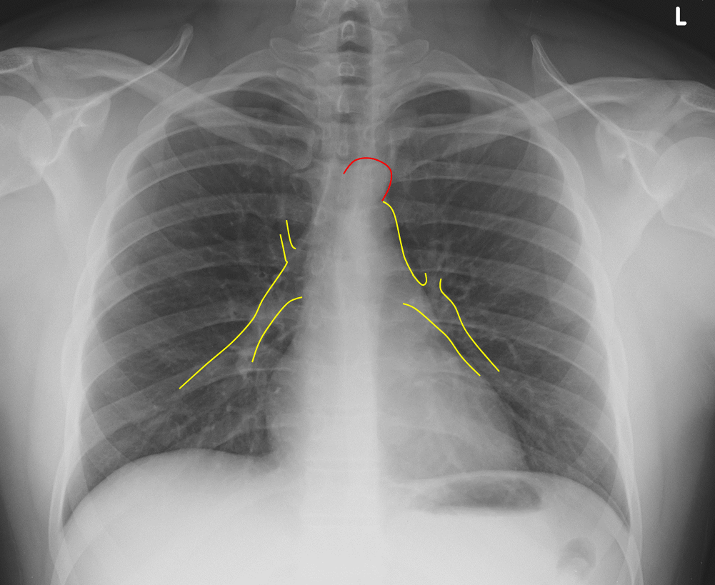
Normal Pulmonary Artery Contour
Section 4: Learn Important Signs
Silhouette Sign
Normally on Xray studies, two adjacent structures are visually distinct from one another because they have different densities. Thus you can see a silhouette of the dense structure against the adjacent less dense structure, for example the cardiac silhouette or diaphragms adjacent to the air containing lungs.
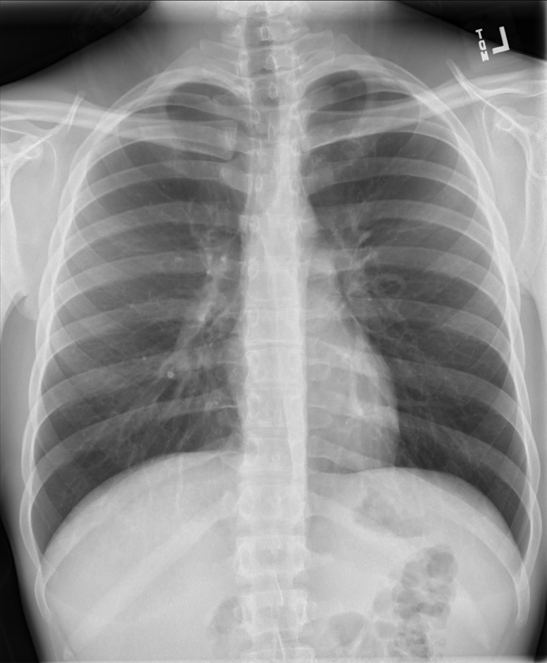
Normal Cardiac Silhouette
If something alters the tissue density, typically the less dense lung becoming more dense due to mass or consolidation, the silhouette may be lost because the adjacent structures are now closer in density.
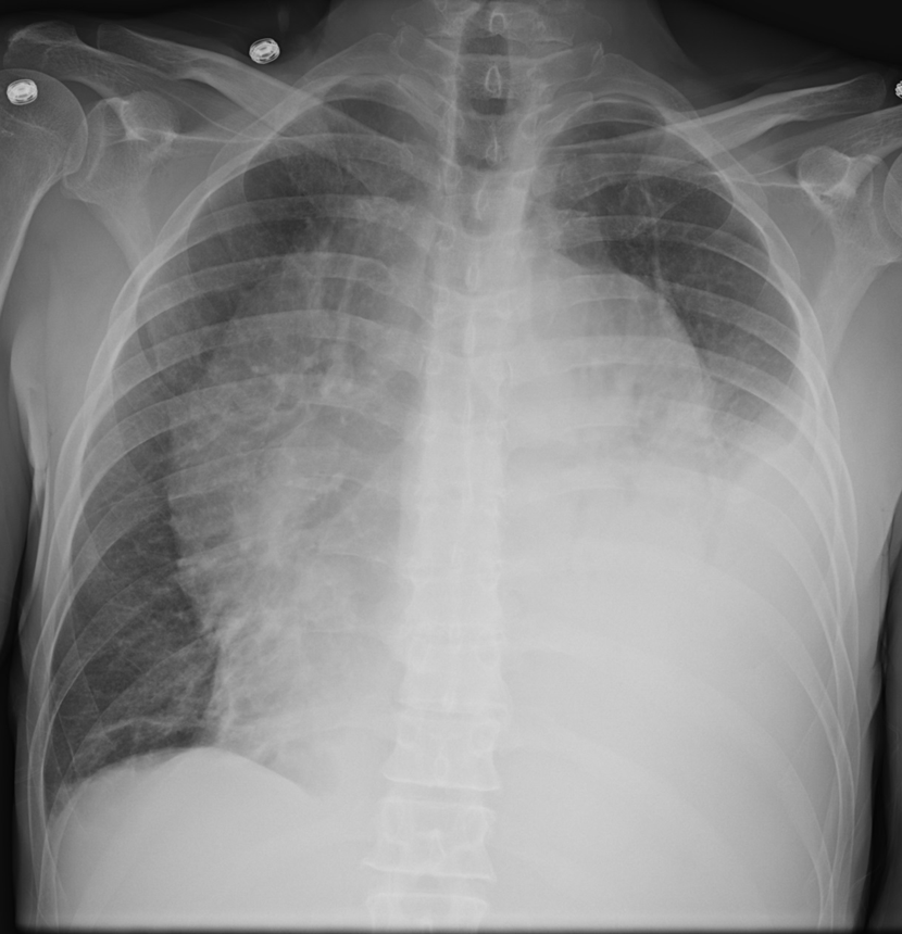
Left Sided Effusion Causing Loss of Cardiac Silhouette
The classic example is a right middle lobe (RML) consolidation. Normally, the right heart border silhouette is seen because it is next to air containing lung. In the presence of a RML consolidation which replaces air with denser inflammatory material, the right heart silhouette is lost.
 |  |
Normal Right Heart Border Loss of Right Heart Border from RML Infiltrate
A right lower lobe consolidation will not result in loss of right heart silhouette because they are not adjacent to each other.
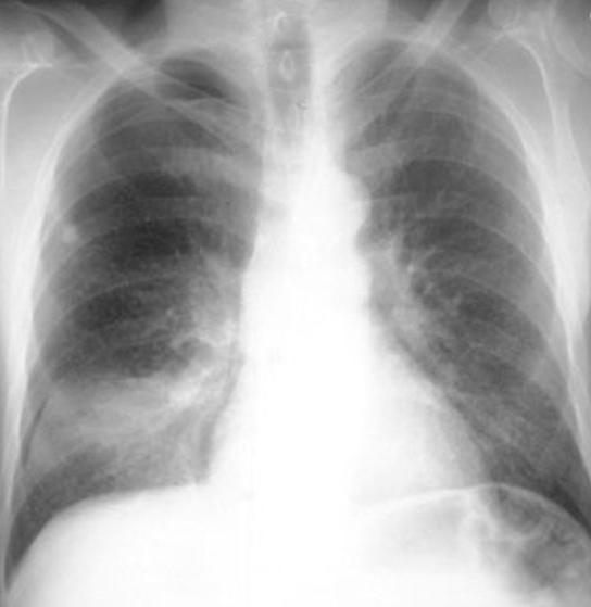
RLL Consolidation – No Loss of Right Heart Border
Sometimes it is not obvious on the PA view which side a consolidation is on because it may be located in the posterior sulcus and therefore obscured.
We can use the lateral view and an understanding of the silhouette sign to help determine when a consolidation is present and which side it is on.
 |  |
“Normal” View of PA and Lateral Chest
Notice how on this normal lateral the diaphragms extend all the way from anterior to posterior. The right diaphragm usually is slightly higher than the left and the left often will not extend fully anterior because of the heart being adjacent to it.
Now notice how the left diaphragm silhouette no longer extends posteriorly all the way. This is because it has lost its silhouette because there is a dense consolidation directly adjacent to it.
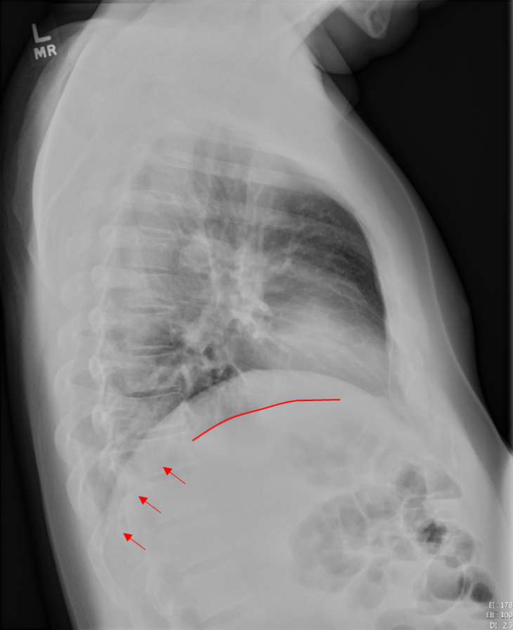
Loss of Left Diaphragm Due to Consolidation
Air Bronchogram
Normally bronchioles are not visible because they are surrounded by air in adjacent alveoli
In the setting of air in the alveoli being displaced by fluid or cellular debris, the air in the bronchioles appears as a translucent tube against the hazy opacity of the affected airspaces.
This can be a clue that a opacity may be due to airspace consolidation and not mass.
 |  |
Air bronchogram sign (enlarged right lower lobe image on right)
Deep Sulcus Sign
In patients who are upright when imaged, such as for a PA/lateral CXR, air in the pleural space from a pneumothorax tends to collect in non-dependent locations, such as the apices.
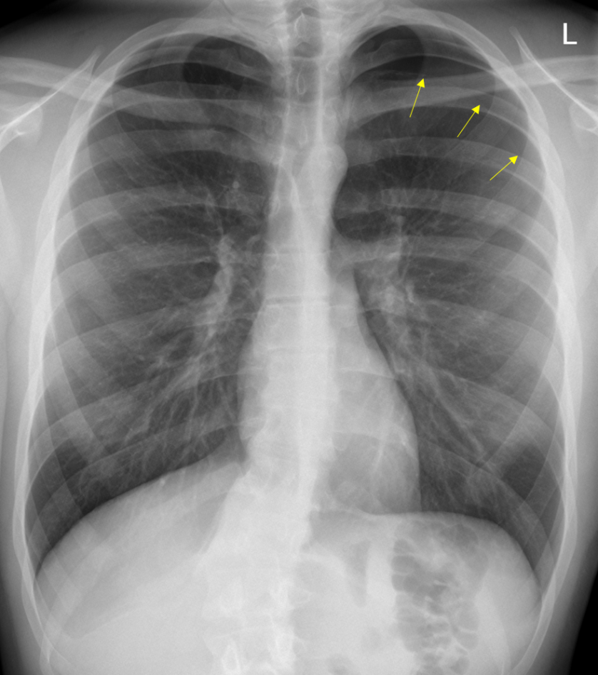
Left Apical Pneumothorax
In patients who are supine, air may collect at the bases and anterior chest, potentially resulting in a deep sulcus sign, which indicates a pneumothorax.
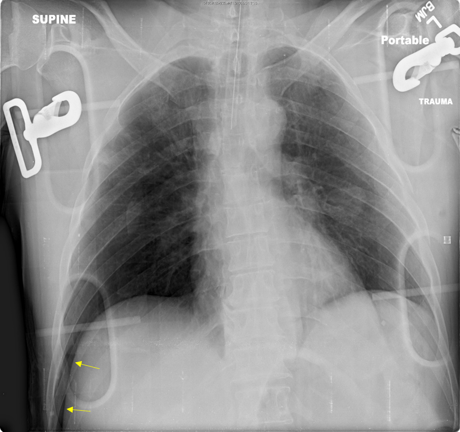
Deep Sulcus on Right (Yellow Arrows) on Supine Radiograph
Continuous Diaphragm Sign
Normally, the central portion of the diaphragm is not visible because it is contiguous with the cardiac silhouette.
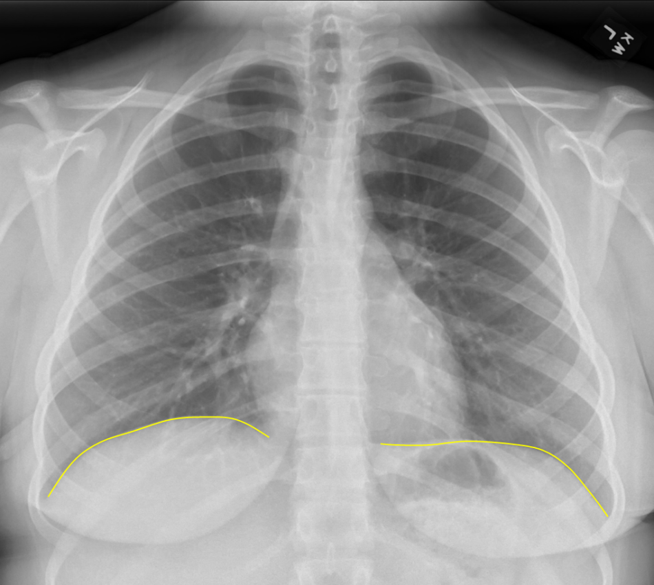
“Normal” Appearance of the Right and Left Diaphragms
If it is visible then it is highly suggestive of free air in the mediastinum or peritoneal cavity.
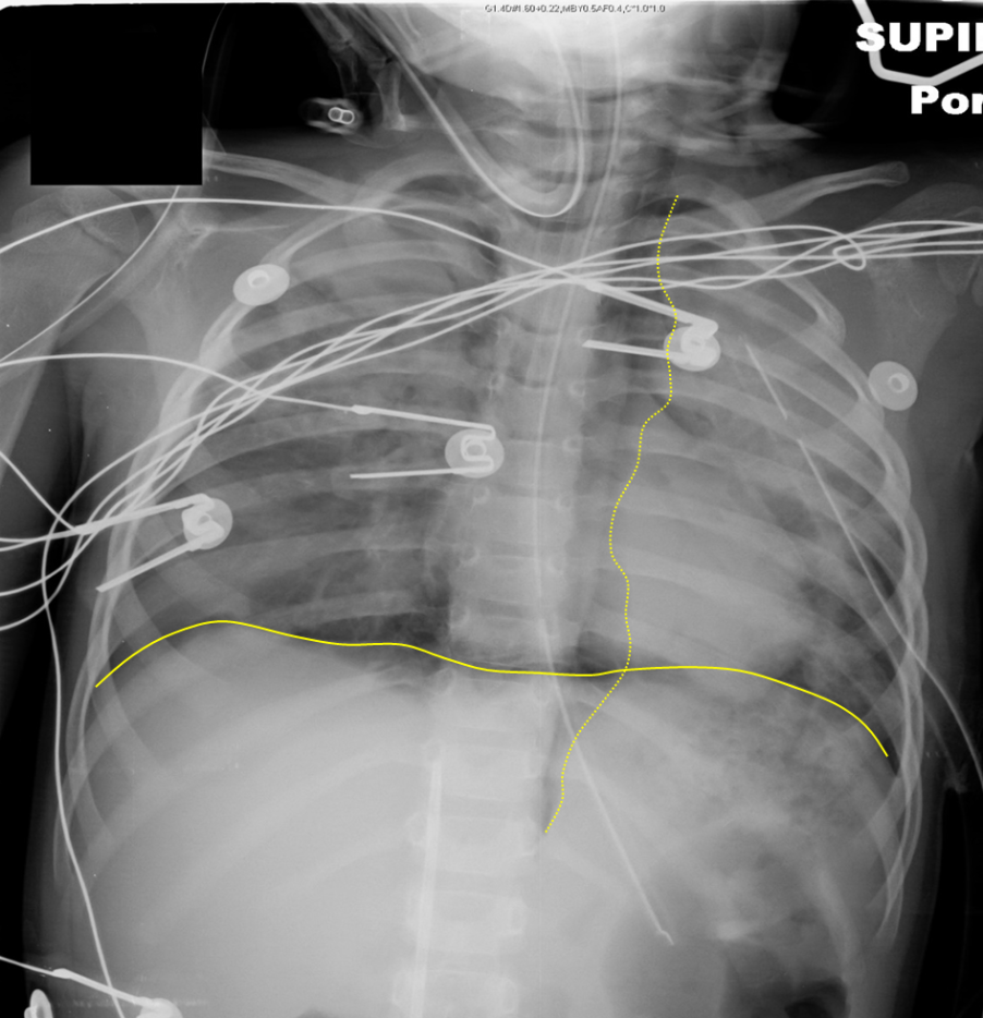
Continuous Diaphragm from Intraperitoneal Free Air
(Dotted yellow line outlines mediastinal air)
References
- Brant, William E, and Clyde Helms. Fundamentals of Diagnostic Radiology, 4th ed. Philadelphia: Lippincott Williams and Wilkins, 2012. Hardback.
- Corne, Jonathan, and Maruti Kumaran. Chest X-Ray Made Easy, 4th ed. Edinburgh: Elsevier, 2015. Paperback.
- Guttentag, Adam. “Basic X-ray Interpretation,” Learning Radiology,http://www.learningradiology.com/lectures/facultylectures/Basic%20Chest%20X-Ray%20Interpretation/player.html.
- Radiology Masterclass, http://www.radiologymasterclass.co.uk/tutorials/tutorials
- Smithuis, Ron and Otto van Delden. “Chest X-Ray – Basic Interpretation,” The Radiology Assistant, http://www.radiologyassistant.nl/en/p497b2a265d96d/chest-x-ray-basic-interpretation.html.
